3D Mode
3D mode turns image colors into physical layers. Prepare the image in 2D, choose dimensions and a print method, then click Build 3D Model. Changing a setting does not rebuild the displayed model automatically.
Use Manual to choose color order and thickness yourself. Use Auto-paint to predict blends from your real filaments and find a stack for the image. Neither method operates the printer: export the model and check it in your slicer.
3D Print Settings
| Control | Effect on the model | What to check |
|---|---|---|
| Pixel Size (XY) | Millimetres per image pixel in both horizontal directions. | The Model badge estimates physical width, height, and depth before building. |
| Layer Height | The regular vertical step used for heights and swaps. | Match the slicer. Smaller layers give finer height choices, not narrower extrusion lines. |
| First Layer Height | The first step above the plate. | Match this separately. The first color must be at least the greater of regular and first-layer heights. |
| Effective line width | The extrusion width used for Auto-paint's printable-detail checks and height dithering. | Match your slicer's intended line width, not nozzle diameter or Pixel Size. It does not change the printer profile. |
| Smooth Meshing | Changes pixel-stepped boundaries to smoothed connected contours. | Changes exported geometry, not just lighting. It does not add image detail or iron the surface. |
| Reset | Restores 0.1 mm/pixel, 0.12 mm regular layers, 0.2 mm first layer, 0.42 mm effective line width, and smoothing off. | Also resets manual thicknesses to minimums, preserving current color order. |
Pixel size is not nozzle size
A 1,000-pixel-wide image at 0.1 mm/pixel produces a model about 100 mm wide. At 0.2 mm/pixel, it becomes about 200 mm wide with exactly the same image pixels. Transparent outer margins are excluded from model bounds.
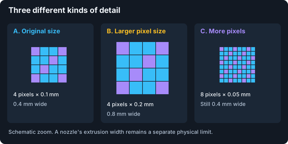
Schematic. XY size, image resolution, and extrusion width are separate controls.
To keep a 100 mm width with 2,000 image pixels, use 0.05 mm/pixel. More pixels can describe finer edges, but the printer still has an extrusion-width limit. Set Effective line width in 3D Print Settings, then use Auto-paint's printable-detail preview to inspect that limitation.
Increasing pixel size does not reduce pixel count or make the mesh inherently cheaper to generate. For a lighter build, resize or crop in 2D mode, or simplify its palette.
Effective line width
Copy the slicer's intended extrusion width into Effective line width. It accepts 0.1 to 2 mm. Resetting 3D Print Settings restores it to 0.42 mm along with the section's other defaults. Editing this field does not change the printer profile.
Auto-paint uses this width for its width-warning preview, optional isolated-color-speck cleanup, and height-dither block size. The controls for inspecting warnings or omitting isolated specks remain in Auto-paint. Warnings do not mean that a feature will be removed or cannot print.
Layer heights and valid boundaries
With a 0.20 mm first layer and 0.08 mm regular layers, layer tops are at 0.20, 0.28, 0.36, and 0.44 mm. They are not 0.08, 0.16, 0.24, and 0.32 mm. Kromacut reconciles color thicknesses to this grid.
Changing Layer Height resets manual thicknesses to the new regular step, then applies the first-color minimum. Changing First Layer Height resets the first color to its new minimum. Set these before tuning sliders and recheck the plan if they change.
The fields accept broad application ranges: 0.01–10 mm/pixel for Pixel Size, 0.01–10 mm for Layer Height, and 0–10 mm for First Layer Height. These are input limits, not recommended printer settings; the first color is still reconciled to its physical minimum. Use values your nozzle, material, and slicer support. A finer height changes Auto-paint's available recipes; it does not automatically make existing calibration compatible.
Manual Mode
Color Slice Heights lists nontransparent Image colors. Each row has a drag handle, color swatch, thickness slider, and millimetre readout. That value is the color run's thickness, not its absolute top height. One run can span several slicer layers.
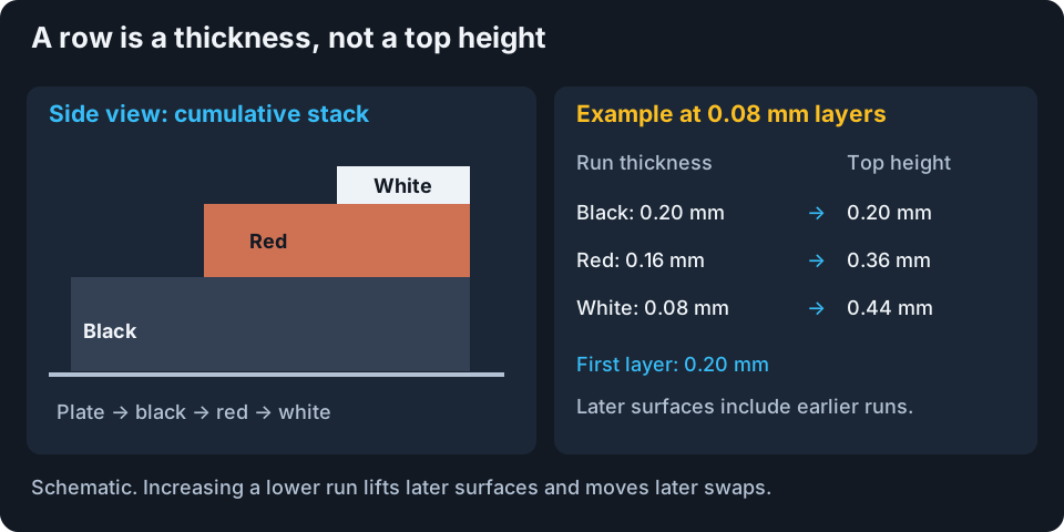
Schematic cross-section. A later-color surface contains earlier runs beneath it.
For example, set black to 0.20 mm, red to 0.16 mm, and white to 0.08 mm, with 0.08 mm regular layers. Black regions stop at 0.20 mm, red at 0.36 mm, and white at 0.44 mm. Red begins on slicer layer 2; white begins on layer 4. Confirm the generated instructions and the slicer's interpretation before printing.
Reorder colors
Drag rows top to bottom in printing order. The top row starts on the plate. Later rows print on earlier ones only where the image needs them, forming stepped relief. Moving a color changes its backing material, surface height, and swap sequence. A row moved into first place is raised to the first-layer minimum when needed.
Manual preview and export use image colors, not the Auto-paint HD model. Thin red over black can print darker than its swatch even when the manual preview looks red. Choose materials and thicknesses accordingly.
Adjust and reset thicknesses
Drag a slider and release to commit. Later runs step by Layer Height. The first starts at its minimum and adds regular steps. Increasing a lower run raises all later surfaces and moves their swaps, not just regions where the lower color remains visible.
The Color Slice Heights reset sorts dark to light by luminance and assigns minimum thicknesses. It differs from resetting 3D Print Settings, which also changes physical print parameters but preserves order.
Manual controls and swap instructions support 64 colors. Reduce larger palettes in 2D. Fully transparent pixels create no material, not white backing. Disconnected opaque islands remain separate pieces unless the image connects them.
Smooth Meshing
With smoothing off, outlines follow the square pixel grid. With it on, connected boundaries are smoothed into welded geometry. The difference is exported, not a preview filter.
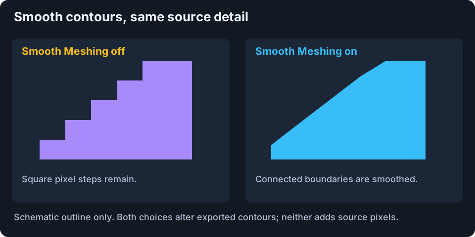
Schematic contour comparison, not a slicer simulation.
Use it for curved or diagonal outlines that look too stair-stepped. Leave it off for deliberate pixel art or exact grid edges. Neither choice repairs unprintably small details or invents missing source resolution.
Smooth Meshing is inactive during Flat Paint. Turning Smooth Meshing on disables Flat Paint; Flat Paint uses its full-footprint slab construction instead.
Auto-paint
Auto-paint accepts real filament colors and Hiding Distance (HD), predicts blends, and maps image colors onto printable heights. Read Auto-paint controls for every filament, matching, detail, and confidence control.
Calibrating Filament Hiding Distance
Calibrate below the filament list opens Hiding Distance, Palette Proof, and Stack Matrix. Follow Calibration workflows for printing and recording results, or Calibration theory for the optical model.
Filament Profiles
Profiles store named filament sets and compatible evidence. Unsaved edits are not automatically written back to the selected profile. See Filaments and profiles and profile files.
Templates
Templates are read-only supplier reference sets, not measurements of your spools. Load, adjust, calibrate, then Save as new profile. See Templates.
Max Height
The cap shortens Auto-paint transitions on valid layer boundaries but cannot remove the opaque foundation. Read Max Height, including the Flat Paint carrier caveat.
Printable Detail
Set Effective line width in 3D Print Settings, then use Open preview in Auto-paint to inspect thin source-color regions. Omit isolated color specks optionally replaces colors used only in tiny enclosed specks, while preserving thin lines and connected detail. Warnings and actual omitted-pixel counts are shown separately. See Printable detail.
Enhanced Color Matching
Search material orders with repeats, distinct-color requirements, or spatial height dithering. These trade color coverage, thickness, swaps, and computation. See Enhanced color matching.
Flat Paint
Make a multi-material slab instead of stepped relief, either face-down with a clear carrier or carrier-free face-up. Read Flat Paint before exporting because viewing direction and object assignments matter.
Optimizer Settings
Algorithm, Region priority, Transition detail, and Seed tune matching, not printer speed. See Optimizer settings.
Transition Zones And Confidence
Zones describe physical runs; confidence describes evidence and modeling limitations, not measured print accuracy. See Reading the result.
Palette Proof
Compare a printed coupon against selected image colors and record which candidates match. See Calibration workflows.
Stack Matrix
Photograph a saved recipe board, verify alignment, and save measured colors for compatible stacks. See Calibration workflows.
Preview Controls
Drag with the primary mouse button to orbit, use the wheel to zoom, and drag with the secondary button to pan. Camera movement never changes physical dimensions.
| Toolbar control | Use it for | Effect on the print |
|---|---|---|
| Color accurate | Compare selected swatches without scene lighting or filmic tone mapping. | Preview only. Still depends on the model and display; not calibration validation. |
| Shaded | Inspect lit relief and shape. | Preview only; lighting changes apparent color. |
| Transparent | See overlapping layers. | Preview only; does not make filament transparent. |
| Wireframe | Inspect layer-colored feature edges. | Preview only; not extrusion toolpaths. |
| Preview colors | Toggle Auto-paint simulated blends versus physical filament colors. | Preview only. Exports keep real material assignments. |
| Camera toggle | Perspective depth versus orthographic alignment without foreshortening. | Preview only. Camera position is retained. |
| Undo / Redo | Step through shared image-edit history. | Not an undo stack for 3D fields or filament edits. Rebuild after an image change. |
| Download | Export the built STL or 3MF. | Uses the last built model, not unapplied sidebar settings. |
View mode and simulated/physical choices are remembered. Preview colors appears only for a built Auto-paint model.
Layer Preview
Drag the bottom bar's lower and upper handles to isolate a height range. Positions snap to the layer grid. Hover over material segments for start or swap information.
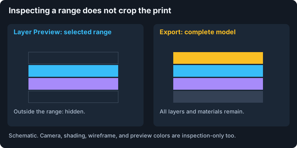
Schematic. Hiding a layer on screen never deletes it from the export.
Flat Paint has a plain track because several materials can occupy one printed layer. Orbit underneath the default face-down layout to see its artwork.
A failed Auto-paint calculation can leave the previous successful build visible. Do not treat it as proof the new settings worked. Print instructions use the built snapshot when one exists. Resolve the error, build again, then inspect and export.
Next: Auto-paint controls, Flat Paint, or Generating and exporting output.