Calibration Workflows
Calibration helps Auto-paint predict what stacked filament will look like. It is not printer calibration: these tools do not tune extrusion, temperatures, bed leveling, or nozzle settings. Use a reliable slicer setup first, then measure the same materials and viewing conditions you intend to use for artwork.
Open 3D → Auto-paint → Calibrate. The dialog contains Hiding Distance, Palette Proof, and Stack Matrix. They measure different things, and can be used together.
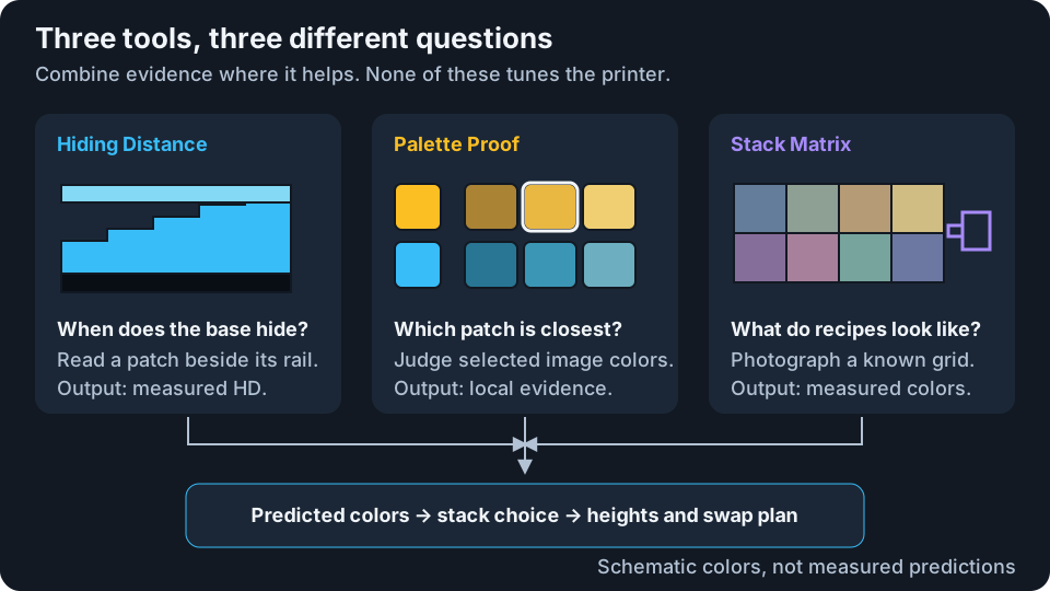
| Tool | Use it when | What you provide | What can change afterward |
|---|---|---|---|
| Hiding Distance | A filament's opacity is unknown or only estimated | The first wedge patch that matches its reference rail | HD, channel estimates, transition thickness, total height, and swap plan |
| Palette Proof | A few colors in one artwork matter most | Closest printed candidates and match quality | Local color predictions and stack preferences; potentially order, heights, and geometry |
| Stack Matrix | You want measured colors for many short recipes | A correctly aligned frontlit photograph | Measured recipe predictions, local interpolation, and a validated physical fit |
None of these tools increases your printer's XY resolution or makes every target color achievable. A well-calibrated profile can still have a limited gamut. For the underlying model, see Calibration theory.
Prepare And Protect Your Filament Profile
A filament row describes a real spool, not a desired image color.
| Control | What it does | Important consequence |
|---|---|---|
| Color swatch / Hex | Sets the filament's nominal opaque color | Changing it deactivates a wedge calibration measured for the old color. It also changes compatibility with saved appearance evidence. |
| Name | Gives the spool a readable label | A label change does not change its optics. Save the edit before tracking proofs or matrices. |
| HD field | Enters frontlit hiding distance in mm, from 0.01 to 2 | A larger HD generally needs more thickness to hide the substrate. Committing a manual value clears the wedge calibration. |
| Convert from TD | Converts a conventional backlit/lithophane TD to HD using approximately TD × 0.1 | Enter a conventional TD here, not in the HD field. The converted value is an estimate and replaces the wedge calibration. |
| Wand | Estimates HD from the swatch color | Useful as a starting point, not a measurement. It replaces any existing wedge calibration. |
| Calibration badge | Shows Estimate, or a measured calibration's quality label | Hover to inspect channel HD values. The label is not a guarantee that a finished artwork will match its source. |
| Add Filament / trash | Adds or removes a spool from the working set | The available physical colors and evidence compatibility can change. |
Use the Profiles toolbar to keep a named, unchanged set before recording appearance evidence:
- Profile dropdown: loads a saved set into the working filaments. Loading another set replaces the current working list, so save any edits you want to keep first.
- Save selected profile: overwrites its filament list with the working values. Existing proof and matrix records are retained, but incompatible records no longer apply to the changed set.
- Save as new profile: creates a separate named filament set. It copies the filament rows and their wedge measurements, not the old profile's proof and matrix history.
- Rename: changes the profile label without changing its measurements.
- Import: loads filament files. Export backs up a clean named profile, including its proof judgments and matrix measurements, as
.kfil. Desktop export opens Save As; web export follows the browser's download behavior. - Delete selected profile: removes the saved profile and its evidence. Export a backup first if you may need it again.
An unsaved changes indicator means the working set differs from the selected profile. Save or overwrite it before creating a matrix or recording proof results. Exporting while dirty creates an “unsaved edits” profile without the old appearance history; it is not a full backup of that history. Templates are read-only starting sets with estimated HD, so save your own copy before calibrating. See profile file formats and import handling.
Hiding Distance: Read A Wedge
1. Select Filaments And Bases
Select one or several filaments, or use Select all / Deselect all, then choose Next: Base.
- Quick uses one base per filament. It measures a scalar opacity threshold and keeps conservative channel differences estimated from the swatch.
- Accurate lets you select up to three bases per filament, initially recommending two useful bases when available. Each base produces a separate wedge read. This refines a constrained channel estimate; it does not independently measure three spectral channels.
- Base swatches choose what prints underneath that filament. Use a contrasting base so the thin patches can visibly differ from the rail. A nearly identical base and filament cannot provide a useful opacity threshold.
Switching Quick/Accurate resets the base selection to the mode's recommendations. Accurate mode is useful when you can compare the same material over more than one substrate, not simply because its name promises a universally better result.
2. Set The Wedge And Print It
| Control | Effect on the calibration print |
|---|---|
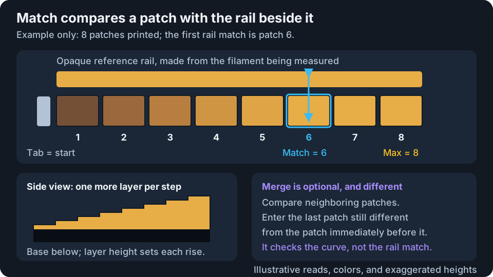
| Layer height (mm) | Sets the thickness of each additional wedge patch layer. The field accepts 0.04–0.40 mm. A finer height gives finer measurement steps but does not make an unsupported printer setup reliable. |
| Max layers (wedge length) | Chooses 4–40 steps. More steps extend the measurable range for translucent filament and make a longer, taller wedge. |
| STL (any printer) | Downloads one uncolored tile. Print a copy for each selected filament/base pair and use the listed manual swap. |
| 3MF (multi-material) | Includes all selected reads with their real filament/base assignments in one file. Verify the slicer's material mapping. |
| Download | Exports the current wedge plan. The results step uses that plan's layer height and base choices, not an unrelated later edit. |
Use the displayed regular layer height, first-layer height, and swap after layer / Z exactly. The first-layer height comes from the print settings; the wedge's own Layer height control is separate from the regular 3D model setting. Do not scale the model in Z. Next: Enter Results opens the reading step; downloading does not send anything to the printer.
On desktop, both wedge formats open Save As; in the browser, they use the normal download behavior. Wait for the export to finish before changing settings or entering results. Cancelling Save As or a failed export leaves the previous successfully downloaded wedge plan unchanged; if saving fails, an error appears so you can retry.
3. Compare And Save
View the printed wedge face-up under your intended front lighting. The tab marks the one-layer end. Compare each patch to the reference rail beside it, not to a phone photograph or an on-screen swatch.
- Match: enter the first patch number that looks identical to the rail. This is a patch's added filament-layer count, not the printer's absolute layer number.
- Merge (optional): enter the last patch that still looked different from the preceding patch. This checks the fitted curve; it is not a second required opacity measurement. A merge value later than Match receives a warning.
- Predicted swatches / HD / confidence / diagnostics: show the result inferred from your reads. These are feedback, not extra measurements you must supply.
- Save calibration: applies complete, usable filament measurements. A blank filament is Not entered and stays unchanged. A partly entered Accurate filament is Won't save until every chosen base has a Match value. You can save other complete filaments without finishing the whole sheet.
If even the last patch differs from the rail, do not call it a match just to finish: make a longer wedge. If the first patch already matches, a finer, printable layer height or a more contrasting base can make the measurement more informative. Reads at the ends of the available range have lower confidence.
Recalibrating a filament replaces its previous wedge result. To combine several bases, read them together in one Accurate session. Save/overwrite the named profile afterward, and export a backup. Measured HD changes both predicted color and the amount of material Auto-paint considers necessary; rebuild and check the new heights and swap instructions.
Back lets you revisit the wizard steps. Closing the dialog resets unsaved wedge selections and reads, so save usable results before leaving. If several complete multi-base reads trigger a session fit, wait for it to finish before saving; the pending calculation is not another measurement you need to enter.
Printed Example: Eight Filaments
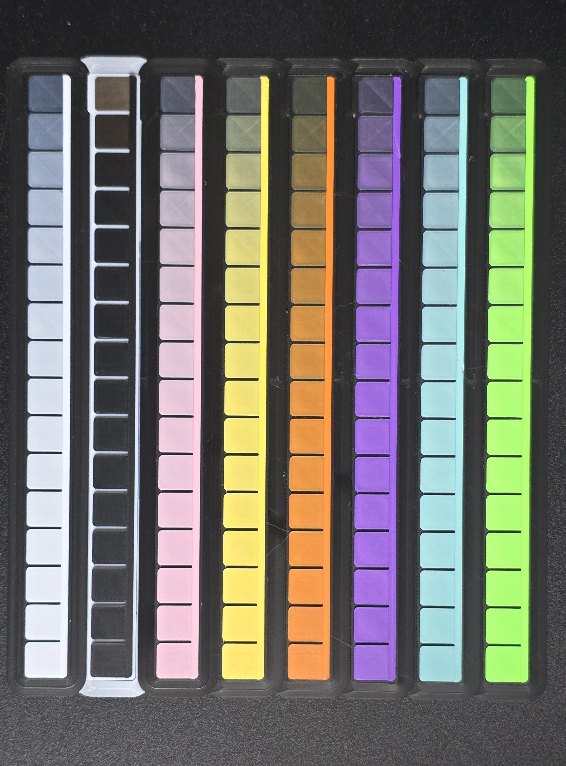
This real calibration print was completed on 13 September 2026. The white and colored wedges use black backing; the black wedge uses white backing. The accompanying 8 Colors 0.2mm profile records 0.04 mm wedge layers and a 0.10 mm first layer. A profile's name does not replace its recorded print settings.
Use the photo to recognize the patch-and-rail layout and the progression toward opacity, not to copy Match numbers or sample calibrated colors. Camera exposure, white balance, lighting, and your display can change the apparent match. Read your own physical print beside its rail under consistent front lighting.
Palette Proof: Compare Artwork Colors
A proof prints several candidates from the current Auto-paint stack. A prefix means the foundation and every layer above it up to a chosen stopping height. Proofs compare printable stopping heights, not arbitrary independent mixtures of the spools.
Choose Targets And Candidates
First let Auto-paint finish computing a result with at least two eligible printable prefixes. You do not need to build the artwork's 3D mesh first. Save its named filament profile, then open Palette Proof.
| Control | Meaning |
|---|---|
| Targets | Number of artwork colors to compare, up to 10 or the number available. The default is 8 when enough colors exist. |
| Candidates | Requested alternatives per target, normally 2–5, bounded by the available useful prefixes. More candidates make the coupon wider. |
| Choose from image | Opens a separate target-selection view. Click important image regions or their color toggles. |
| Original image | Targets the processed image colors before appearance fitting, not the untouched uploaded photograph. |
| Fitted / achievable | Targets the exact predicted colors used by the current Auto-paint result. Use this to ask whether the print matches the preview; the word achievable does not certify physical accuracy. |
| Total proof targets | Sets the same target count while choosing from the image. |
| Clear selections | Removes manual priorities and returns the open slots to smart selection. |
| Use smart targets / Use chosen + smart | Returns to the proof with your priorities, filling remaining slots automatically. |
Selected colors stay bright wherever they occur in the image; unselected regions dim. Picking a target does not recolor the source or force it into the printer's gamut. Reducing the target count can drop priorities beyond that count.
Print And Identify The Coupon
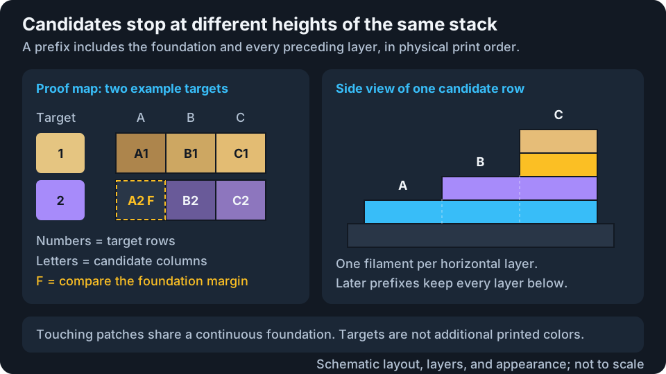
The Proof map and Results views use one target per row, with candidates A–E running left to right. Numbers identify the target row. F means the shared foundation reference, not a sixth candidate color or another filament. Compare it to the exposed foundation margin.
Download 3MF exports the coupon and, for a clean named profile, saves its identity and recipe map. After saving, the target selection and counts are locked so results cannot silently refer to a different print. Keep it face-up at 100% scale, use the embedded regular and first-layer heights, verify filament assignments, and use the missing top-left corner to orient it. The default 8-target × 5-candidate coupon is 44 × 68 mm. It has touching 8 mm patches over a continuous foundation, so boundaries can be less obvious than in the on-screen grid.
Record What You Actually See
Open Results, compare the printed candidates with the displayed target under consistent viewing conditions, and select the closest patch. Select multiple patches if tied. Then describe the match:
| Answer | What it tells Kromacut |
|---|---|
| Best available | This is the least-wrong option. Support it relative to the alternatives without claiming it equals the target. |
| Close | The chosen color is nearly right. Add a soft local correction as well as the preference. |
| Dead on | The chosen recipe accurately matches this target. Keep the strongest local anchor, with the lower layers needed to reproduce its visible color. |
| None | Every candidate is clearly poor. Reject these choices locally without inventing a correct color or selecting a winner. |
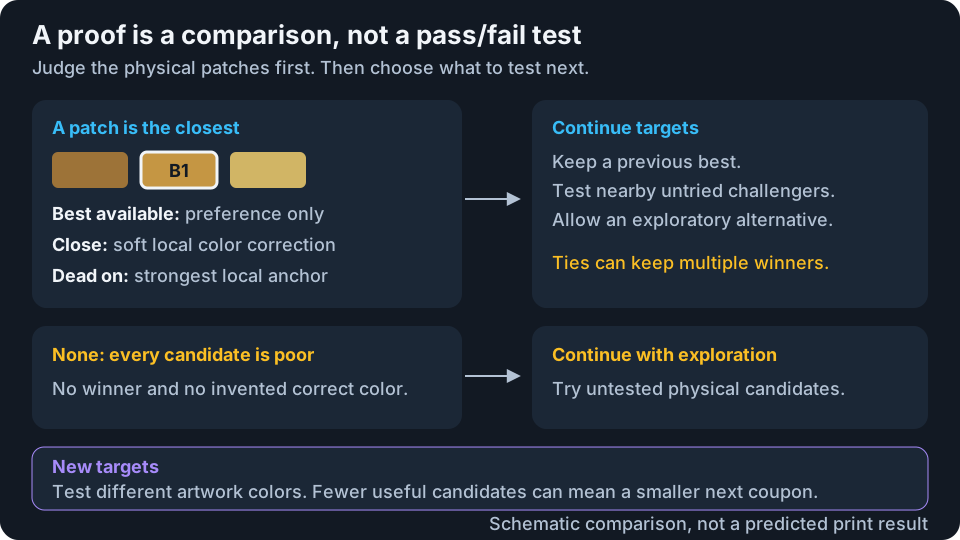
Answers persist as you enter them. Complete results becomes available when every row is answered, including None answers. Edit results reopens a completed proof for corrections. The saved-proof dropdown groups matching target sets and their continuation rounds.
- Continue targets: prints another round for the same targets using the current compatible stack. It retains selected previous bests, tests nearby untried challengers, and can include one exploratory stack. A None answer has no previous-best anchor, so the next round explores alternatives.
- New targets: opens image selection for another target set. Smart selection favors colors outside the completed proof, then less-tested colors.
- Fewer candidates / exhausted targets: the search does not fill the board with unrelated repeats merely to meet your requested size. Read the warning; fewer useful choices do not mean your calibration was lost.
- Delete proof: after confirmation, removes that saved coupon and all its judgments from appearance evidence.
Saved results remain readable without the original image. Downloading a saved proof again requires its exact source Auto-paint snapshot; continuing targets needs a compatible current artwork/process. Retain the original 3MF if you may want to reprint it later.
Proof judgments can alter nearby predicted colors, stack rankings, and eventually printed heights. They do not change the actual material assigned to exported layers or overwrite the spool's HD calibration. A single result does not establish a globally accurate palette. The broader fit has evidence and held-out validation gates; local judgments can be useful even when that fit is not active.
Stack Matrix: Photograph Known Recipes
Plan The Board
Save an unchanged named profile first. Set the intended Layer Height and First Layer Height in 3D print settings before selecting New matrix. The Hiding Distance wedge's layer-height field does not control matrices.
| Control | Effect on the board |
|---|---|
| Filament swatches | Select 2–8 filaments in profile order. Only these materials supply recipe layers. |
| Max color thickness (mm) | Caps the color region above the one-layer foundation. Rounded down to whole regular print layers, from 1 to 64 layers. At 0.04 mm, a 0.40 mm cap allows recipes up to 10 layers. |
| Maximum cells | Caps the number of recipes: 64, 144, 256, 400, 625, 1,024, 1,296, 1,600, or 2,025. A larger board samples more recipes but uses more bed area and printing time. |
| Planned material-change budget | Limits the planner's material-change estimate, including the corner references. Choose 40–640 changes or No planner limit. This is not a duration estimate or a guarantee of the slicer's final swap count. |
| Backing filament | Chooses a selected filament for the one-layer foundation and padding under shorter recipes. It defaults to the lightest selected filament. A thin first layer is not guaranteed opaque. |
| Layer height / First layer height | Read-only confirmation of the live 3D settings for a new board. |
| Recipe / size / height / swap summary | Shows the footprint, foundation + color-region height, total height, and print-layer count before download. The saved board reports its frozen heights, selected cells, planned changes, references, and prior boards considered. |
| Create and download 3MF | Plans recipes, exports the board, then records the saved plan in the profile. |
New boards use adaptive coverage: a bounded, repeatable search samples recipes across the allowed thickness range. It favors gaps in previously measured colors, untested depths and filament transitions, and exploratory recipes where predictions have little support or previously disagreed with measurements. Predicted novelty is not a promise that the printed color will be new. A few reference cells deliberately repeat so successive photographs can be compared.
Only completed boards with compatible profile/material data, backing, print heights, and accepted photo alignment guide the next board. Downloading an unprinted plan does not make its colors measured. Keep your completed boards: choosing New matrix automatically considers eligible measurements. Changing the backing or print settings can start a separate coverage context.
New boards have a one-layer foundation, driven by First Layer Height, without an additional opacity-based slab. For example, a 0.10 mm first layer + 0.40 mm color region = 0.50 mm total height. At 0.04 mm regular layers, that is 11 print layers: one foundation layer and ten color-region layers. The height summary shows this breakdown before download and uses the actual stored foundation when viewing an older board.
All patches still finish at one flat top surface. A shorter recipe sits on extra layers of the same backing filament, beneath the color layers, inside the color-thickness cap. This padding does not add to the total height shown. The saved record preserves both the useful recipe and its backing padding.
A thin first layer is not automatically opaque. Choose an opaque backing filament and photograph the board on a consistent, flat backing surface; light or color showing through from beneath can affect the measured colors. Extra backing can only be treated as optically neutral once it genuinely hides what is underneath.
Measurements over a still-translucent base retain their physical backing thickness. They can support a matching physical stack, but are not used as interchangeable measurements over different backing thicknesses or to fit the global opaque-backing model. Padding may make some patches opaque even when the bare first layer is not.
New boards group similar recipes together to make same-color regions more continuous and reduce fragmented toolpaths. Grouping does not by itself reduce how many filaments are used on each print layer, so it is not a promise of fewer material changes or a particular time saving. Existing saved boards keep their original cell positions so their photographs still match.
The thickness cap does not force every recipe to use that much color. The cell and material-change budgets can produce fewer cells than requested, and a tight change budget can leave some selected filaments unused; the saved plan warns when this happens. If even the reference patches exceed the change budget, increase the budget or reduce the thickness cap or filament selection. Deeper boards and CFS/AMS purges can remain slow even with few cells: inspect the final slicer estimate before printing.
The saved summary counts selected recipes that have not been measured in compatible prior boards. If that count is zero, the plan only repeats existing measurements; you can skip printing it and try different limits or materials. This does not prove that every achievable color has been measured, because the search is bounded.
Cells are fixed at 5 mm and gapless, with an added marker border; for example, a 32 × 32 data grid occupies a 170 × 170 mm board. Older saved boards retain their fixed recipe depth and all combinations or HD-selected gamut labels; re-downloading them does not convert them to the adaptive format.
On desktop, cancelling Save As does not create a new saved plan. In the browser, the plan is recorded when the download starts. Check for storage-error messages, and keep the 3MF. A saved board freezes its layer heights, backing, and recipe map: later setting changes do not redesign it, and Download 3MF on that record exports the original board again.
Print face-up at 100% scale with the exact layer heights and filament assignments. A first layer below the regular layer height is normalized to the regular height. The foundation remains one layer at that effective first-layer height; it is not thickened to reach an opacity target. Older saved boards retain their original foundation, including any extra foundation layers. This is a physical calibration artifact, so changing its Z scale or material mapping invalidates what the cells are supposed to measure.
Load And Align A Photo
Select the printed board in the saved-matrix dropdown, then Choose photo or drop an image onto the photo area. Photograph under diffuse front lighting without strong glare. The file must be decodable by the app; a camera RAW file is not a substitute for a normally viewable image export.
| Control | What it changes |
|---|---|
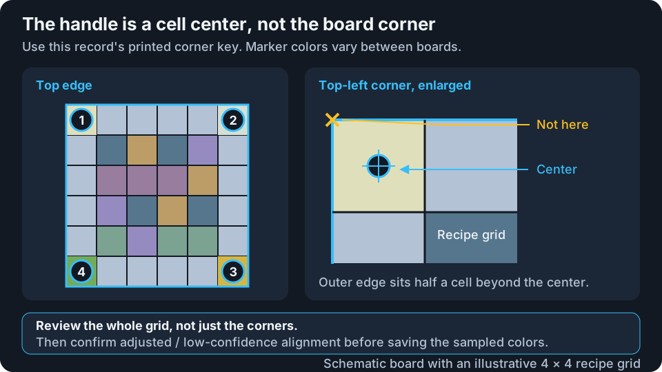
| Printed corner key | Shows the required orientation: 1 top-left, 2 top-right, 3 bottom-right, 4 bottom-left. Follow this record's swatch colors, which vary with the chosen filaments. |
| Rotate left / right | Turns the uploaded photo by 90° and reruns detection. It does not change the saved physical recipe map. |
| Zoom − / percentage / Zoom + | Changes inspection magnification from 100% to 400%. At 100%, the whole photo fits the workspace; it is not a one-screen-pixel-per-camera-pixel view. Click the percentage to reset and scroll to reach enlarged areas. |
| Four numbered handles | Drag to the centers of the colored marker cells diagonally outside the dense data grid. The loupe crosshair marks the sampled center. |
| Show template grid | Shows projected cell boundaries so you can compare them with the print. This is a review overlay, not a color correction. |
| Detect again | Re-estimates alignment from the current photo. |
| Reset | Restores the initial estimate for the current photo, undoing manual handle adjustments. It does not delete a saved calibration. |
| I verified every grid line and marker center | Required after manual adjustment or low-confidence detection. Confirm only after checking the full grid and all four centers. |
Do not place handles on the last recipe cells or on the physical outside corners. The blue board outline should extend half a cell beyond each marker center. Check the Perspective-corrected preview: cells should look square and match the printed layout. The app samples inset centers to avoid cell boundaries, but a shifted grid still assigns the wrong colors to recipes.
Decide How To Sample, Then Save
Reference marker correction is off by default. Off retains the photograph's sampled colors, including its camera color cast. On applies per-channel gains estimated by comparing the four photographed markers with their predicted recipe colors. It can reduce a broad cast or brightness bias, but it does not independently measure the room's lighting and does not repair shadows or glare. Incorrect marker predictions can also bias the result. A brighter preview is not proof of a more accurate measurement.
The Extracted LUT preview shows the colors that will be stored, one swatch per recipe. Hover a cell to see its sampled RGB values. Compare this with the physical board and your intended viewing conditions, not with an expectation that every cell should be vivid.
Save calibration becomes available once the samples and alignment review are ready. On a completed record the button reads Replace calibration and replaces that record's photographed measurements; download/export a backup first if you want to retain both versions. The saved profile contains colors and recipe data, plus photo metadata, not the original photo itself. Keep your source photo separately if you may need to resample it later.
New matrix starts another board; Back to saved matrices returns to existing records. Delete Stack Matrix removes the selected board and its evidence. Completed compatible boards can contribute together, so you do not need to delete an older board just because you measured a new one.
Which Evidence Applies To My Next Print?
| Evidence | Compatibility to check |
|---|---|
| Wedge HD | Belongs to the measured filament color. HD is a thickness model rather than a lookup of one layer count; new print settings still deserve a physical check. |
| Palette Proof preferences and broader fit | Require the same ordered filament identities, colors, HD/calibration data, regular layer height, first-layer height, and transition-opacity setting. |
| Dead-on proof anchors | Require the matching filament/profile and layer heights. They can remain eligible when transition detail changes, provided the required physical suffix is realizable. |
| Stack Matrix | Requires a completed, accepted alignment, compatible filament/profile data, and the same regular layer height. Exact recipe use additionally depends on the measured backing or supported optical equivalence. |
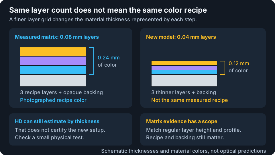
Changing from 0.08 to 0.04 mm does not reinterpret a photographed three-layer recipe as six layers. That matrix is outside the new regular-layer-height context. The selected profile may still provide wedge HD estimates, but the Appearance model can correctly report Estimated only and zero Matrix LUT recipes.
A different first-layer height does not automatically disable every matrix. Matrices preserve their original foundation, and reuse depends on whether the generated backing meets the measured or supported-equivalent conditions. Do not assume that the same top filament, or the same total thickness, is enough. See prediction uncertainty for the bounded backing-transfer and same-filament continuation rules.
Read Confidence Without Overclaiming Accuracy
The filament badge, Result Confidence, and Appearance model / Prediction confidence describe different things:
- Filament confidence concerns how well a wedge measurement was constrained. Edge-of-range reads, disagreement, or aging reduce it. Estimate means no active wedge measurement.
- Result Confidence combines Calibration, Coverage, and Compression. A high aggregate can coexist with entirely simulated recipe colors.
- Appearance model identifies available empirical evidence and fitting status. Counts of compared stacks, anchors, local neighborhoods, and Matrix LUT recipes tell you what actually informed the run.
- Prediction confidence describes the support for the colors mapped into this image, including measured, interpolated, fitted, or simulated predictions. A measured recipe is still a camera or human observation under particular conditions, not a laboratory guarantee.
Use Best available, not Dead on, when choosing the least-bad proof patch. Do not keep adjusting a matrix photograph until the preview looks attractive. The useful next step is a small physical test that checks the colors and print settings you actually changed.