Generating And Exporting Output
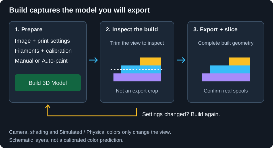
The export workflow starts after your 2D image and 3D controls are ready.
Before You Export
Check these items:
- In 2D mode, reduce the image to a practical number of colors.
- In 3D Print Settings, choose the physical dimensions with Pixel Size (XY). Match Layer Height and First Layer Height to your slicer, and Effective line width to the planned extrusion width for Auto-paint's printable-detail checks and height dithering.
- Choose Manual or Auto-paint.
- Click Build 3D Model.
- Inspect the model and the Layer Preview.
If Kromacut shows a Performance Warning, the build may be slow because of image size, pixel count, layer count, or similar workload. You can continue with Build Anyway or cancel and simplify the job.
Build 3D Model
Click Build 3D Model whenever you want the preview and export geometry to reflect current 3D settings.
While building, Kromacut shows progress such as reading image color layers, mapping image colors, or building color layers. Export controls become useful again once the overlay disappears and the updated model is ready to inspect.
Auto-paint calculating a new stack is not the same as building a new mesh. Export uses the last built model, and Print Instructions stays tied to that build. After editing the image, changing a profile, saving calibration, or changing print settings, wait for the current calculation and build again before exporting. A previous preview can remain visible while new settings are being computed or rejected; its presence does not prove that the new settings succeeded.
Choose STL Or 3MF
Open the 3D download menu and choose:
| Format | Use it when |
|---|---|
| STL | You want a widely supported single-geometry model and will handle filament swaps manually. |
| 3MF | You want color-aware output for slicers that can preserve multiple colored objects. |
3MF export preserves physical filament colors in Auto-paint where possible. Still review slicer assignments before printing.
An Auto-paint preview may show dozens of blended colors made from only a few real spools. The 3MF assigns those real filaments to the physical layers, not one material per predicted blend. A slicer's ordinary filament-color view can therefore look different from Kromacut's Simulated view without the material assignments being wrong. Compare against Physical colors when checking assignments.
STL does not carry filament colors or automatic spool assignments. Use the copied swap plan with the slicer's color-change controls. A 3MF is still a model, not ready-to-run G-code: choose your own printer, nozzle, filament profiles, temperatures and speeds, then slice it.
For Flat Paint models the download menu offers only 3MF: the model contains one object per physical filament and, in the default face-down layout, a transparent carrier object. The optional face-up layout omits that carrier. An uncolored single-geometry STL of either flat slab would be useless. Flat Paint turns off Smooth Meshing because the flat slab layout does not use smoothed boundary contours.
Print Instructions
The Print Instructions panel gives you:
- Recommended wall loops, infill, layer height, and first-layer height.
- Start with Color.
- Color Swap Plan with layer numbers and approximate heights.
- A Copy button for the full plain-text plan.
Use the copied plan beside your slicer preview. The layer numbers depend on Layer Height and First Layer Height, so keep those values consistent.
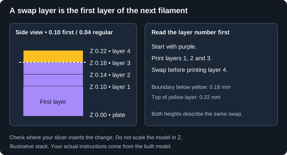
Swap at layer N means the new filament prints layer N. For example, with a 0.10 mm first layer and 0.04 mm regular layers, layers 1, 2 and 3 finish at 0.10, 0.14 and 0.18 mm. To start the next filament at layer 4, change it after layer 3, before extruding layer 4. That new layer finishes at 0.22 mm.
The approximate height in the plan needs care: the Manual path shows the new layer's top Z, while Auto-paint shows the material-change boundary. Use the layer number and inspect the actual sliced material transition, not just a matching-looking Z number. Slicers can label the selected layer and the insertion point differently.
In Flat Paint mode there is no manual swap plan. The panel instead summarizes the selected multi-material workflow: assign each 3MF object to its filament, then either use clear filament and flip the default face-down print or print the carrier-free layout face-up. Neither layout should be mirrored in the slicer.
Recommended Slicer Setup
Kromacut recommends:
- Wall loops:
1 - Infill:
100% - Layer height: the value shown in Print Instructions
- First layer height: the value shown in Print Instructions
Always inspect the slicer preview before printing. Heights are approximate, and slicers can display layer changes differently depending on first-layer settings.
Keep the export at 100% Z scale and use a constant layer height matching the model. Changing Z scale or enabling variable layer height moves the physical transitions and invalidates the copied plan. If you need a different layer height, set it in Kromacut and rebuild. Changing XY scale also changes printable detail relative to the nozzle; set the intended size in Kromacut so its line-width check uses that size.
Review small islands, text, disconnected transparent cutouts, foundations and the purge/prime arrangement in the slicer. Smoothing contours cannot make every narrow stroke printable. The app does not calibrate your printer's flow, retraction, temperature or mechanical setup.
Saving And Cancelling
Desktop file exports open a Save As dialog. In a browser they use the browser's download settings, so whether you see a location prompt depends on the browser. Cancelling a file dialog does not send anything to the printer. During export, geometry writing and archive compression can take time; wait for saving to finish before closing the app.
Export Tips
- Build the model after changing 3D settings.
- Do not rely only on the visible layer preview trim; export includes the full model.
- If the mesh is too heavy to build or slice, crop or downsample the source in 2D and reduce unnecessary color regions. Increasing Pixel Size (XY) enlarges the same pixels; it does not reduce their number or simplify the mesh.
- If swap instructions are disabled because there are too many colors, return to Reducing colors.
Next: Settings and controls.